Rover (Toy Car) Tutorial
What you'll be building
This tutorial teaches you how to build a rover that can be driven using your mobile phone. It includes a live video feed and a control interface for driving. Since the rover and your phone both have internet access, the toy car can be controlled from across the world.Requirements and Materials
- Raspberry Pi connected to the internet
- Raspberry Pi camera
- Raspberry Pi OS (Buster)
- Chassis Components: Zumo chassis kit, 2 micro motors, L298N module, 4 AA batteries
- External Power Source, for example the Anker PowerCore+ Mini
- Wires, tape, foam packing material, rubber bands
Step 1: Build the Chassis
Follow the first 6 minutes and 15 seconds of this tutorial video to build the chassis.
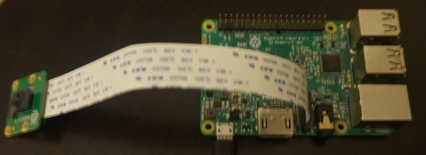
Step 2: Add the Raspberry Pi and L298N Module
Cut out a piece of foam to act as a cushion between the Raspberry Pi and chassis, and another piece of foam to sit between the Raspberry Pi and L298N Module. Then attach them to the chassis using rubber bands. Connect the Raspberry Pi Camera.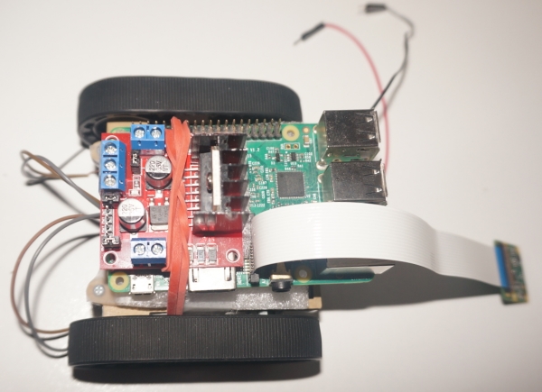
Step 3: Connect the Circuit
Connect the motors to the sides of the L298N module. Connect pins 19, 20, 21, and 26 to the control pins of the L298N module. Connect a ground wire between the Raspberry Pi and the L298N module, and finally connect the batteries (located underneath the chassis) to the L298N's ground and +12V.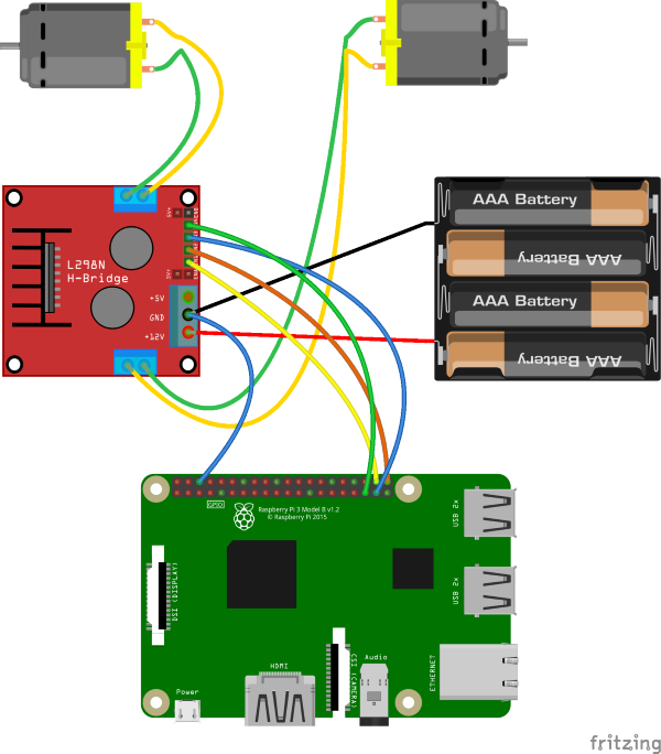
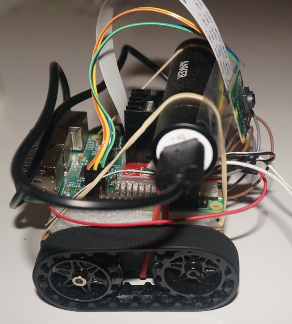
Add some foam insulation under the external power source, and secure it using rubber bands. Tape the camera to the device to prevent it from moving while driving. Connect the power source to the Raspberry Pi, and add the wheel treads if you haven't done so already.
Step 4: Enable the camera
The camera must be enabled on the Raspberry Pi using the command:sudo raspi-config
Visit the official documentation for more info.
Step 5: Run LimitOS on the Raspberry Pi
LimitOS runs on top of Raspberry Pi OS (Buster), and can be run via:curl -sS https://limitos.com/run | bash
Follow the on-screen instructions to register the device afterwards.

Step 6: Enable LimitOS video
Edit your device by selecting "My Devices" above, clicking on the device, and then clicking "Edit Device".Make sure to check the "Enable live video" checkbox.
If your video appears upside down, you can also come back here later to invert the video.
Step 7: Set up the Pins
On your LimitOS device page, add pins 19, 20, 21, and 26 as the "output - digital" pin type. Test out each pin individually using the controls at the bottom of the page, and then name each pin accordingly.
Step 8: Set up the Control Interface
Click the icon next to "Device Controls" to access the control interface. Click the gear icon to edit the interface, select the "Drive" control template, allow public access if you'd like, and then map your pins appropriately and save the changes.